Diodes#
A junction diode is made by placing N-type semiconductor right next to P-type. The boundary separating the two types is called a bipolar junction.
Fig. 1 Circuit diagram symbol for diode.#
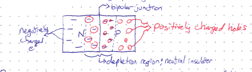
Random thermal motions and slight electric attraction draw some of the free electrons from the N side and fill the holes on the P side. Similarly, the positive holes move to the N side and neutralize with a free electron. The migration of charges creates a neutral region in the middle of the diode, which now acts as an insulator and disallows further charge movement across the bipolar junction. The neutral region in known as the depletion zone.
What happens when voltage is applied across a diode? We will examine two scenarios. For now, ignore the resistors in the circuit diagrams. We will discuss their purpose later on.
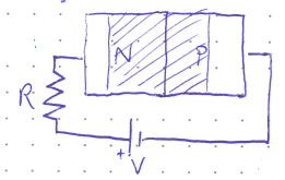
Forward Bias#
A diode is forward biased when the positive terminal of the voltage source is connected to the P-type half of the diode. In this mode, positive holes in the P-type region are repelled by the positive terminal and pushed toward the central depletion region. Similarly, electrons in the N-type half are also pushed toward the depletion region. This shrinks the depletion region!
While the central depletion region is still a neutral insulator, it is now much easier for electrons to jump over the small potential barrier because the region is so thin. As long as the applied voltage is larger than some threshold, current can flow through the diode. For standard silicon diodes, the threshold voltage (\(V_\gamma\)) is approximately 0.7 V.
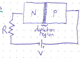
Reverse Bias#
A diode is reverse biased when the positive voltage terminal is connected to the N-type half of the diode. Here, the opposite of forward biasing happens. Free charge carriers are attracted towards the voltage source and away from the center of the diode. This expands the neutral depletion region, and no current can flow unless a very, very large voltage is applied. This is called the breakdown voltage and is similar to the example of lightning coursing through the atmosphere. Reaching breakdown voltage will usually destroy the diode.
In normal operation, diodes are one way streets for current. Current will only flow through the diode when it is forward biased. No current will flow when it is reverse biased.
IV Relation for Diodes#
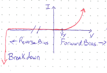
Compare the forward biased IV relation of a diode with that from a resistor. Whereas the current through a resistor increased linearly with applied voltage, current increases exponentially in a diode. Very large currents are, in general, bad, and will lead to your circuit melting. Always make sure there is a current limiting resistor attached in series with a diode. (Typical values of 220 \(\Omega\) will work in most cases, but refer to the data sheets if unsure.)
Note the break in scale in the reverse bias region. Breakdown does not occur until very large voltages.
Light Emitting Diodes (LEDs)#
LEDs are diodes that are designed to emit photons of a specific wavelength when electrons fill in the positive holes. The wavelength of light is determined by the materials used to make the semiconductors, the same way fireworks achieve different colors using different materials. Because LEDs use different materials, many of them have different threshold voltages than the standard 0.7 V.
LEDs have had an immense positive impact on humanity as they generate light withough consuming much power or generating much heat.