Basic Circuit Components#
Let’s review the components of a simple direct current (DC) circuit.
1. Voltage#
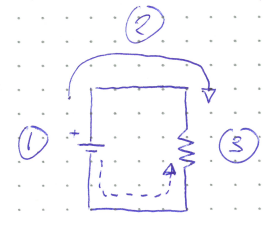
The part labelled 1 is a DC voltage source (commonly implemented with a battery). The long bar represents the high voltage terminal (sometimes, but not always, emphasized with a “+” sign), and the short bar is the low voltage terminal. In some cases where multiple DC sources are stacked together, the symbol will also be stacked together.
Voltage (\(V\)) is a measure of potential energy per charge. It is often referred to simply as potential and has units of Volts (V). You can think of Voltage as being somewhat similar to gravitational potential. Just as a ball on top of a hill rolls down to the lowest gravitational potential, current (see the next section) flows from high voltage to low voltage. The battery or voltage source acts as a pump to make sure that current can keep flowing, bringing it back up to a high potential so it can fall down again.
DC means that current will only ever flow in one direction around the circuit. There are also alternating current sources where the current flows in both directions, but they are almost never used in digital electronics for reasons that will become apparent once we discuss diodes and transistors.
2. Current#
The solid arrow labelled 2 shows the flow of current (\(I\)) through the circuit. Current is a measure of the flow rate of charges, and has units of Amperes (Amps or A). Unfortunately, electrons (e-) were not yet discovered when circuits were first being studied, and so the conventional current actually shows the flow of positive charges. In reality, electrons move in the opposite direction (from low Voltage to high) as shown by the dashed arrow. However, this is theoretically equivalent to the positive flow model.
The current flows through wires represented by the solid straight lines connecting the components. The wires are assumed to be perfect, meaning that the Voltage and current are the same at any point along a continuous wire, and the resistance (described in the next section) is zero. The connecting wires could be drawn longer or shorter, and it would not alter our interpretation of the circuit diagram. While this assumption is not entirely realistic, copper wires are close enough to perfect when the lengths are relatively short (on the order of a meter or less).
3. Resistance#
The zig-zag symbol is a resistor. It provides resistance (\(R\)), which is a measure of how difficult iti is for current to flow. It can be thought of as similar to friction, or to the diameter of a pipe, but neither of these analogies is entirely accurate. Resistance has units of Ohms (\(\Omega\)).
In lab, we will use resistors often. It is important to know how to read them. They look like cylinders with various coloured bands.
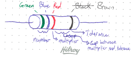
The first two bands define a number for the resistance, and the third band is a multiplier. This is very similar to scientific notation, but note that there is no decimal in the two digit number. In the image above, green means 5, blue means 6, red means a multiplier of \(10^2\), so the total resistance is \(56 \times 10^2 = 5600 \Omega\).
After the multiplier, there is a gap, and then the final band tells us the manufacturing tolerance for the resistance. In this case, brown means the resistor is \(5600 \Omega \pm 1\%\). In rare cases, you may find resistors with only three coloured bands. In this case, the default tolerance is \(\pm 20\%\). There are also resistors with more than 4 bands, in which case more number bands are included to add mor significant figures.
The following table shows how to interpret the different coloured bands depending on where they lie on the resistor.
Colour |
Number |
Multiplier |
Tolerance |
|---|---|---|---|
Black |
0 |
\(10^0\) |
— |
Brown |
1 |
\(10^1\) |
1% |
Red |
2 |
\(10^2\) |
2% |
Orange |
3 |
\(10^3\) |
— |
Yellow |
4 |
\(10^4\) |
— |
Green |
5 |
\(10^5\) |
0.5% |
Blue |
6 |
\(10^6\) |
0.25% |
Violet |
7 |
\(10^7\) |
0.10% |
Gray |
8 |
\(10^8\) |
0.05% |
White |
9 |
\(10^9\) |
— |
Gold |
— |
\(10^-1\) |
5% |
Silver |
— |
\(10^-2\) |
10% |
Aside: How are resistors made?
First, it must be understood that even conductors have some resistance, and that the resistance is directly proportional to the length of the conductor, and inversely proportional to the cross-sectional area (think of the pipe analogy).
By devising a manner where both \(l\) and \(A\) can be controlled, the resistance can be arbitrarily set. Typical resistors start with a cylindrical core made from an insulator (\(R \to \infty\)). The corse is coated with a thin conducting layer (\(R << \infty\), but still non-zero). A spiral pattern is etched out of the conductor, forcing current to flow around and around the insulating core.
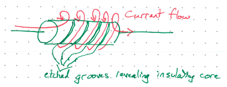
By varying the width and pitch angle of the spiral, both \(l\) and \(A\) can be controlled, and hence the value of \(R\)!